Sunday, December 15, 2013

The Final Post

Tears were shed, blood was lost, sleep was deprived. The design project for 22.201 is now finished.
Description of Final Assembly
The completed project is just as described before. We have a 3X3X3 LED cube wired into a PCB with an acrylic casing covering the whole assembly. This cube then sits on top of a motion mechanism. This mechanism consists of one small servo motor mounted on top of a bigger servo. Using the 3D printer parts were fabricated for this mechanism. Manufactured parts included two servo casings, a bracket, and a platform. In addition to these printed part there were five sides to the LED cube that were laser cut out of acrylic. As for inputs into the whole system there were two potentiometers and one microphone. Each of the potentiometers controlled on of the servo motors. The microphone was used to control the LED cube. Sounds that the microphone picked up triggered a certain pattern based on the volume.
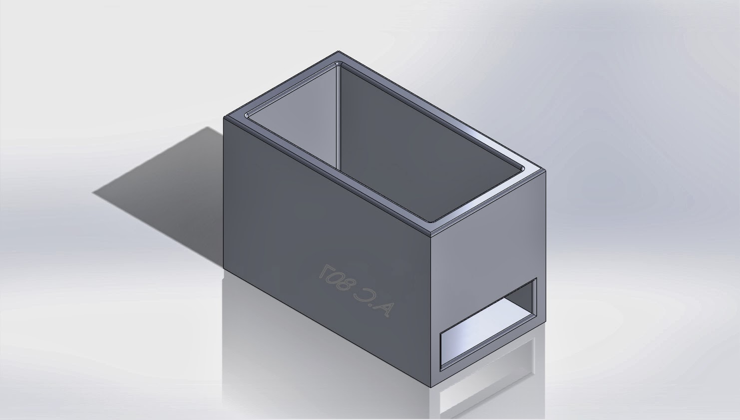
Overall the project did what we set out to do. LED lights were controlled by a microphone, with motion provided by the servos.During transportation to the showcase the 'platform' part broke and was unable to be fitted back to the small servo. Because of this we couldn't fully test the motion of the cube. The following is a picture of the completed assembly:


Below are the final versions of the code used. One for LED control the other for servo control

#include <Servo.h>
Servo myservo; // create servo object to control a servo
Servo myservo1; // create servo object to control a servo
int potpin = 0; // analog pin used to connect the potentiometer
int potpin1 = 1; // analog pin used to connect the potentiometer
int val; // variable to read the value from the analog pin
int valu;
void setup()
{
myservo.attach(9); // SMALL attaches the servo on pin 9 to the servo object
myservo1.attach(10); // BIG attaches the servo on pin 10 to the servo object
}
void loop()
{
val = analogRead(potpin); // reads the value of the potentiometer (value between 0 and 1023)
valu = analogRead(potpin1); // reads the value of the potentiometer (value between 0 and 1023)
val = map(val, 0, 1023, 0, 179);
valu = map(valu, 0, 1023, 0, 179); // scale it to use it with the servo (value between 0 and 180)
myservo.write(val); // sets the servo position according to the scaled value
myservo1.write(valu); // sets the servo position according to the scaled value
delay(15); // waits for the servo to get there
}


// 22.201
// Code for controlling LED cube with microphone
// *******************************
// MIC
const int ledPin = 12; //the code will flash the LED in pin 12
const int middleValue = 512; //the middle of the range of analog values
const int numberOfSamples = 128; //how many readings will be taken each time
int sample; //the value read from microphone each time
long signal; //the reading once you have removed DC offset
long averageReading; //the average of that loop of readings
long runningAverage=0; //the running average of calculated values
const int averagedOver= 16; //how quickly new values affect running average
//bigger numbers mean slower
const int threshold=400;
// **********************************
// Row control
int ledRow1 = 13; //Row 1
int ledRow2 = 12; //Row 2
int ledRow3 = 11; //Row 3
//Cols 1,2,3 + Rows can control LEDS 1-9
int ledCol1 = 9;
int ledCol2 = 8;
int ledCol3 = 7;
//Cols 4,5,6 + Rows can control LEDS 10-12
int ledCol4 = 6;
int ledCol5 = 5;
int ledCol6 = 4;
//Cols 4,5,6 + Rows can control LEDS 10-12
int ledCol7 = 3;
int ledCol8 = 2;
int ledCol9 = 1;
//define the LED cube size
int rowmax = 3;
int colmax = 9;
//making an array
int ledCol[9];
int ledRow[3];
// the setup routine runs once when you press reset:
void setup() {
//***************************
// Microphone Setup
Serial.begin(9600);
//*****************************
//used for random value
//Serial.begin(9600);
// initialize the digital pin as an output.
//3 rows
pinMode(ledRow1, OUTPUT); //Top
pinMode(ledRow2, OUTPUT); //Middle
pinMode(ledRow3, OUTPUT); //Bottom
//9 Columns
pinMode(ledCol1, OUTPUT); //Left
pinMode(ledCol2, OUTPUT); //Middle
pinMode(ledCol3, OUTPUT); //Right
pinMode(ledCol4, OUTPUT); //Left
pinMode(ledCol5, OUTPUT); //Middle
pinMode(ledCol6, OUTPUT); //Right
pinMode(ledCol7, OUTPUT); //Left
pinMode(ledCol8, OUTPUT); //Middle
pinMode(ledCol9, OUTPUT); //Right
//fill array
ledCol[0] = ledCol1;
ledCol[1] = ledCol2;
ledCol[2] = ledCol3;
ledCol[3] = ledCol4;
ledCol[4] = ledCol5;
ledCol[5] = ledCol6;
ledCol[6] = ledCol7;
ledCol[7] = ledCol8;
ledCol[8] = ledCol9;
ledRow[0] = ledRow1;
ledRow[1] = ledRow2;
ledRow[2] = ledRow3;
}
void loop() {
//***************************
// MIC
long sumOfSquares = 0;
for (int i=0; i<numberOfSamples; i++) { //take many readings and average them
sample = analogRead(0); //take a reading
signal = (sample - middleValue); //work out its offset from the center
signal *= signal; //square it to make all values positive
sumOfSquares += signal; //add to the total
}
averageReading = sumOfSquares/numberOfSamples; //calculate running average
runningAverage=(((averagedOver-1)*runningAverage)+averageReading)/averagedOver;
Serial.println(runningAverage);
//****************************************
// PATTERN CODE
delay(100);
if ((runningAverage>1500) && (runningAverage <2000))
{
rainLight();
}
delay (100);
if ((runningAverage>2000) && (runningAverage <2500))
{
lightning();
}
delay (100);
//rainMed();
//delay (2000);
//lightning();
delay (100);
if (runningAverage > 2500)
{
rainHeavy();
}
}
// ************************************************
// FUNCTIONS FOR ALL PATTERNS
// FUNCTIONS!!!!!
//All helper functions used to create designs and patters throughout the loop
//LED movements
//flashes both top and bottom panes
void lightning(){
topPaneOn();
bottomPaneOn();
delay(25);
topPaneOff();
bottomPaneOff();
delay(100);
topPaneOn();
bottomPaneOn();
delay(25);
topPaneOff();
bottomPaneOff();
topPaneOn();
bottomPaneOn();
delay(25);
topPaneOff();
bottomPaneOff();
delay(100);
}
//animate
//Heavy rain
void rainHeavy(){
int del = 80;
int del2 = 60;
randomSeed(analogRead(0)%10);
//Serial.println("Analog input"); //testing
//Serial.println(analogRead(0)%10); //testing
for(int x= 0; x<50; x++){
int stCol = random(0,colmax);
int stCol2 = random(0,colmax);
int stCol3 = random(0,colmax);
int stCol4 = random(0,colmax);
int dropNum = random(0,9);
//Serial.println(dropNum); //testing
for(int y=rowmax-1;y>-1;y--){
if(y==rowmax-1) del2 = 80; //if first row
onLED(ledRow[y], ledCol[stCol]);
if(dropNum>=4){
onLED(ledRow[y], ledCol[stCol2]);
}
if(dropNum>=7){
onLED(ledRow[y], ledCol[stCol3]);
}
if(dropNum>=8){
onLED(ledRow[y], ledCol[stCol4]);
}
delay(del2);
//turn off all even if they wern't turned on.
offLED(ledRow[y], ledCol[stCol]);
offLED(ledRow[y], ledCol[stCol2]);
offLED(ledRow[y], ledCol[stCol3]);
offLED(ledRow[y], ledCol[stCol4]);
del2=30;
}
delay(del);
}
}
//animate
//light rain
void rainLight(){
int del = 170;
int del2 = 70;
for(int x= 0; x<20; x++){
int stCol = random(0,colmax);
for(int y=rowmax-1;y>-1;y--){
if(y==rowmax-1) del2 = 110;
onLED(ledRow[y], ledCol[stCol]);
delay(del2);
offLED(ledRow[y], ledCol[stCol]);
del2=70;
}
delay(del);
}
}
//static
void topPaneOn(){
digitalWrite(ledRow1, HIGH);
digitalWrite(ledCol1, HIGH);
digitalWrite(ledCol2, HIGH);
digitalWrite(ledCol3, HIGH);
digitalWrite(ledCol4, HIGH);
digitalWrite(ledCol5, HIGH);
digitalWrite(ledCol6, HIGH);
digitalWrite(ledCol7, HIGH);
digitalWrite(ledCol8, HIGH);
digitalWrite(ledCol9, HIGH);
}
void topPaneOff(){
digitalWrite(ledRow1, LOW);
digitalWrite(ledCol1, LOW);
digitalWrite(ledCol2, LOW);
digitalWrite(ledCol3, LOW);
digitalWrite(ledCol4, LOW);
digitalWrite(ledCol5, LOW);
digitalWrite(ledCol6, LOW);
digitalWrite(ledCol7, LOW);
digitalWrite(ledCol8, LOW);
digitalWrite(ledCol9, LOW);
}
/*
//static
void middleTBPaneOn(){
digitalWrite(ledRow2, HIGH);
digitalWrite(ledCol1, HIGH);
digitalWrite(ledCol2, HIGH);
digitalWrite(ledCol3, HIGH);
digitalWrite(ledCol4, HIGH);
digitalWrite(ledCol5, HIGH);
digitalWrite(ledCol6, HIGH);
digitalWrite(ledCol7, HIGH);
digitalWrite(ledCol8, HIGH);
digitalWrite(ledCol9, HIGH);
}
void middleTBPaneOff(){
digitalWrite(ledRow2, LOW);
digitalWrite(ledCol1, LOW);
digitalWrite(ledCol2, LOW);
digitalWrite(ledCol3, LOW);
digitalWrite(ledCol4, LOW);
digitalWrite(ledCol5, LOW);
digitalWrite(ledCol6, LOW);
digitalWrite(ledCol7, LOW);
digitalWrite(ledCol8, LOW);
digitalWrite(ledCol9, LOW);
}
*/
void bottomPaneOn(){
digitalWrite(ledRow3, HIGH);
digitalWrite(ledCol1, HIGH);
digitalWrite(ledCol2, HIGH);
digitalWrite(ledCol3, HIGH);
digitalWrite(ledCol4, HIGH);
digitalWrite(ledCol5, HIGH);
digitalWrite(ledCol6, HIGH);
digitalWrite(ledCol7, HIGH);
digitalWrite(ledCol8, HIGH);
digitalWrite(ledCol9, HIGH);
}
void bottomPaneOff(){
digitalWrite(ledRow3, LOW);
digitalWrite(ledCol1, LOW);
digitalWrite(ledCol2, LOW);
digitalWrite(ledCol3, LOW);
digitalWrite(ledCol4, LOW);
digitalWrite(ledCol5, LOW);
digitalWrite(ledCol6, LOW);
digitalWrite(ledCol7, LOW);
digitalWrite(ledCol8, LOW);
digitalWrite(ledCol9, LOW);
}
//turn on LED based on row number and column number
void onLED(int row, int col){
digitalWrite(row, HIGH); //turn on row
digitalWrite(col, HIGH); //turn on col
}
//overload funtion - used to turn LED on with certain intensity
void onLED(int row, int col, int value){
digitalWrite(row, HIGH); //turn on row
analogWrite(col, value); //turn on col
}
//turn off LED based on row number and column number
void offLED(int row, int col){
digitalWrite(row, LOW); //turn on row
digitalWrite(col, LOW); //turn on col
}
Improvements
With this being the first design iteration there are many improvements that could be made. The following is a list of things that could be better developed.
  • Write in a break statement into the LED pattern code so every time the value of the microphone changes the code breaks out of its current pattern and starts a new one. This will give a more responsive LED cube. 
  • Code the microphone to read the music being played not only the volume. The microphone would read the music frequency band spectrum. This way the LED cube could react to the type of music being played. Things like tempo and pitch would be a factor in LED display.
  • Upgrade the second level small servo to a bigger one to provide more motion.
  •  Refine the whole motion mechanism. Currently it is very primitive with just the servos stacked on top of one another. Create better solid models that fit together. The thickness of the extrude needs to be increased to be stronger on the 'platform' 3D printed part. 
  • Write code for the microphone so it calibrates itself upon start up. This would calibrate it with the surrounding environment. Within the first 5 seconds the microphone would take the lowest and highest values and used those as threshold values to run the LED patterns.
  •  Better assembly of the LED cube. Use longer more flexible wires; use a coupling to organize all the wires underneath the cube. Have holes in the acrylic cube for the wires.
  • Replace all the red and yellow LEDs with RGB LEDs for a more colorful performance.
  • Map microphone data to control both servos. This would give a completely self-sufficient system, instead of having user input control.  

Team Member Contributions:

Jennifer Droke:

  • Design of acrylic cube casing. Created SolidWorks models for a visual of the final assembly, as well as for having the part made.
  • Designed wiring layout for LED cube based on tutorial http://randomnerdtutorials.com/arduino-led-cube-3x3x3/
  • Assembled, soldered, and tested LED Cube 
  • Assembled acrylic casing from cut parts
  • Soldered wiring on PCB
  • Purchased the proper transistors, resistors, jumper wires, PCB, and microphone for the cube, as well as materials for the project board and the potentiometers for the  servo motors
  • Assembled final prototype for presentation
  • Created tri-fold project board and researched/typed information for presentation
  • Wrote about four blog posts, contributed to one other. Made multiple pictures and videos for blog.
  • Estimation of total hours worked: 35 hours
My thoughts: Our group worked together very well, and we all contributed equally.  Every meeting, we were all deep in work and maintained open communication.  If anyone missed a meeting, the work was quickly and easily made up with all the hours put in at home.  It was great working with two exceptional team members who worked to make our final prototype work just as we wanted it to in our original idea.


Matthew Popelka:

  • Design of the motion mechanism using the servos. Created all necessary solid models on SolidWorks.Converted to STL file type and checked part material. Then redesigned accordingly to reduce material cost and manufacturing time.
  • Purchased bigger servo to ensure smooth motion of LED cube.
  • Modified/integrated the microphone code with the LED control code. Debugged code so patterns would display with correct threshold levels.
  • Wrote about 6 blog spots
  • Edited/finished final report
  • Estimation of total hours worked: 35 hours
My thoughts: I believe everyone contributed fairly and pulled their own weight, we worked well as team. During the team meetings we were all researching, wiring circuits, and discussing. I will say that Jen had the harder task of soldering, wiring, and assembling the LED cube and should be credited accordingly. 

Samir Meskinaoui:

  • Wrote and modified code for the two servo. Harness Arduino component like the potentiometer to control the motion of two servos.
  •   Estimation of total hours worked: 35 hours
  • Edited/started final report.
  • Wrote about 3 blog spots.
  • Search for Arduino codes for the both the servos and microphone and checking all circuits. 
My thoughts: I have worked in many groups in my college career. For the first time, I felt like the group was fair and everyone pulled their weight equally. We all enjoyed creating and learning the new material. Jenn did an excellent job of assembling the LEDs. 

Thursday, December 12, 2013

Wiring and Fun Stuff

Our wiring before we put everything in the final setup. We have two arduinos in series, the one on the right running two servos and the one on the left running the led cube and its microphone.


Wednesday, December 11, 2013

New Power Source!!

Our power source for both boards, the servos, and the cube has arrived. We are now running a 12 volt battery pack of 8 AA alkaline batteries, attached to the master board via the ground and vin pins. Based on our research, vin is the pin used for power input of 7-12 volts and should sustain all of the components of our project.

Battery pack with wires soldered in place.

Led cube and microphone being powered by battery pack.


Video of the Working Cube with Microphone

The video of the cube lighting up to the sound heard by the microphone (finally)! In the final layout, we will use a 12 volt battery pack rather than the power supplied by the computer via usb cable. As seen in the video, our lack of higher voltage from the usb causes some leds to be dim, if they light up at all.


The Final Stretch

This week is probably the busiest for the whole project due to everything finally coming together.

There were setbacks with the assembly of the 3X3X3 LED cube. Initial tests failed to achieve desired results. We couldn't even get a single LED to light up. After many many hours of struggle, checking the wiring, soldering, and assembly, finally today the LED cube lit up and displayed a pattern.

The parts requested for manufacturing have been picked up. The following are the 3D printed parts. There were some problems with two of the parts fitting together. Using a Swiss Army knife excess material was removed sufficiently so that the parts could slide together without interference. This error was caused by a misunderstanding of printer resolution and not having a large enough clearance gap between the parts.

Big Servo Casing
Bracket

Small Servo Casing

Platform


Modular Parts that Fit Together


As far as connections go between all the parts in the assembly. An adhesive will be used such as acrylic glue or epoxy. 
The final steps include integrating the microphone code with the LED cube visual display code and assembling all the pieces together.


Tuesday, December 3, 2013

Project Update

Summary of Progress

Team Meeting
Tuesday 12/3/2013
2pm Perry 321
All team members present

As the Fall 2013 semester draws to a close the project is slowly coming to completion.

Two new pieces of hardware have been acquired for the project: a microphone and a standard servo. The standard servo was purchased with the concern that the micro servo could not handle the weight load of the mechanism. So too ensure some movement a bigger servo was purchased. Specification differences: 1.5 kg/cm@4.8 volts compared to 3.5 kg/cm@4.8 volts. Links to products below:

http://www.adafruit.com/products/1063?gclid=CKXlq8GzlbsCFcY7Mgod1iYABw

http://www.radioshack.com/product/index.jsp?productId=22472146

Status

Part 1:
This week part files for manufacturing were submitted. One set for the acrylic laser cutter and the other for 3D printer. A total of 10 individual parts will be manufactured. The following are some images of the parts, with links to the part files on the drive below.


In one of the previous posts there was the first design iteration of the mechanism, which is used to move the LED cube. The completed assembly could not fully go through the motions necessary, that issue has been resolved. The video below shows a preview of the motion the completed project should go through. Note that servo motors only have a range of 160 degrees, the final project will not have the full range of motion as in the video.


Part 2:
With the microphone finally in hand, the task now turned to controlling the LED with the microphone. Initially there was trouble getting the microphone the produce proper variable outputs. But by using the serial monitor window from the Arduino software we were able to see to exact input data the microphone was gathering from the environment. In the end we learned the microphone was not as sensitive as we thought. In the long run this is better because it gives us a bigger noise level to program for LED output. After many trials the following is the code:


const int sampleWindow = 50; // Sample window width in mS (50 mS = 20Hz)
unsigned int sample;
const int ledPin = 12;
void setup()
{
Serial.begin(9600);
pinMode(ledPin, OUTPUT);
}
void loop()
{
unsigned long startMillis= millis(); // Start of sample window
unsigned int peakToPeak = 0; // peak-to-peak level
unsigned int signalMax = 0;
unsigned int signalMin = 1024;
// collect data for 50 mS
while (millis() - startMillis < sampleWindow)
{
sample = analogRead(0);
if (sample < 1024) // toss out spurious readings
{
if (sample > signalMax)
{
signalMax = sample; // save just the max levels
}
else if (sample < signalMin)
{
signalMin = sample; // save just the min levels
}
}
}
peakToPeak = signalMax - signalMin; // max - min = peak-peak amplitude
double volts = (peakToPeak * 3.3) / 1024; // convert to volts
Serial.println(volts);
delay (200);
if (volts>2){
digitalWrite(12, HIGH);
}
else {
digitalWrite(12, LOW);
}
}
view raw microphone code hosted with ❤ by GitHub

 Final Steps:
 
 For next meeting the following are some items that need to get done:

- Write code for mapping the microphone input to the 3X3X3 LED cube. This is significantly harder than just lighting up one LED. Initial consensus is that we will treat each level separately, like three separate LEDs, instead of trying to light up each of the 27 LEDs individually.

- Buy the right glue for assembly of the final project. The acrylic cube, and some of thee plastic parts will be glued together.

- With the acquisition of the bigger servo a second Arduino board will need to be used. The bigger servo draws 4.8 volts out of 5 total. This will be accomplished by either having a stand alone board or having one be the master controller.

- Monday December 9th is presentation day for the project. The final report needs to be written along with some type of presentation material.


Tuesday, November 26, 2013

The Cube So Far

Here are a few pictures of the construction of the LED cube.

       Soldering each level of the cube using cardboard to hold the LEDs in the specific layout.

The first two levels soldered together.

Completed cube soldered.

Cube soldered to circuit board.


Thursday, November 21, 2013

First Draft of Solid Models

Draft of acrylic cube solid model, made so that our circuit board snaps in place as the bottom of the cube.  Following this model is a front view of the acrylic cube with the LEDs laid out in the proper shape.  For the LEDS, files for red and yellow LED drawings were found on GrabCad and used.


The following solid models were created for the servo-motion-mechanism. A solid model of a servo was downloaded from  GrabCad . The following are images of a bracket that will hold a servo motor, and the corresponding platform that will hold either another servo or the LED cube.


This is a link to a google drive folder with the solid models.


This is a video of the assembly in motion. There were technical difficulties getting the second motor to produce motion of the top bracket. Solidworks outputted an error message of " Simulation cannot continue" We hope to have this problem solved soon and have a proper assembly motion analysis done.


These are very rough solid models and will need to be furthur refined.

Wednesday, November 20, 2013


Post # 5

Third Team Meeting
11/21/2013
Wednesday 2pm, Perry 311
All team members present

Summary:

The parts that we'll be using are:

                                  2 decent servo motors that have 180 degree turning radius
                                  27 LED light
                                  2 PIC16F690-E/P
                                  1 ATmega328 microcontroller
A code was generated for the two servo control with separate potentiometer:

#include <Servo.h>
Servo myservo; // create servo object to control a servo
Servo myservo1; // create servo object to control a servo
int potpin = 0; // analog pin used to connect the potentiometer
int potpin1 = 1; // analog pin used to connect the potentiometer
int val; // variable to read the value from the analog pin
int valu;
void setup()
{
myservo.attach(9); // attaches the servo on pin 9 to the servo object
myservo1.attach(6); // attaches the servo on pin 9 to the servo object
}
void loop()
{
val = analogRead(potpin); // reads the value of the potentiometer (value between 0 and 1023)
valu = analogRead(potpin1); // reads the value of the potentiometer (value between 0 and 1023)
val = map(val, 0, 1023, 0, 179);
valu = map(valu, 0, 1023, 0, 179); // scale it to use it with the servo (value between 0 and 180)
myservo.write(val); // sets the servo position according to the scaled value
myservo1.write(valu); // sets the servo position according to the scaled value
delay(15); // waits for the servo to get there
}
view raw gistfile1.txt hosted with ❤ by GitHub

Thursday, November 14, 2013

Post#4


Post # 4

Third Team Meeting
11/14/2013
Thursday 2pm, Perry 311
All team members present

Summary:
We discuss today in our meeting couple important section in our final project. We did start looking on the detail of the 3X3X3 LED box but taking what we will need to accomplish this task. First, we need to figure out the hardware needed for this part. Second, how we will control the LED with Arduino and how we will setup 27 LED combine controlled with singular Arduino board or multiples boards. the challenges on this part is the limitation of pins  in the  Arduino board.

Parts Required:
  • 1x Arduino Board
  • 27x LED’s
  • 1x Stripboard
  • 3x 22k ohm Resistors
  • 9x 220 ohm Resistors
  • 3x NPN Transistors (for example: 2N2222, BC547, 2N3904)
  • Wire

Schematics:


Arduino code for 3x3x3 LED :


/*******************************************************************************************
3 X 3 X 3 Single Color LED Cube
cube built by Hassan Ali
Started on June 26 2012
www.islandByte.com
Cube built for multiplexing - using 3 pins and 3 transistors to contorl the rows 1-3
And using 9 pins to control the Coloums 1-9
This gives Arduino control of 27 LEDS by using only 12 pins.
*******************************************************************************************/
/*
Layout for the 3x3x3 cube
Row 1 = Top layer, 9 LEDs
Row 2 = Middle Layer, 9 LEDs
Row 3 = Bottom layer, 9 LEDs
Col 1 = Front Left 3 LEDS 1 top, 2 middle, 3 bottom
Col 2 = Front Middle 3 LEDS 4 top, 5 middle, 6 bottom
Col 3 = Front Right 3 LEDS 7 top, 8 middle, 9 bottom
****need to complete this documentation
Col 4 = Middle Right 3 LEDS - 8 top, 9 middle, 10 bottom
Col 3 = Front Right 3 LEDS 7 top, 8 middle, 9 bottom
*/
// Row control
int ledRow1 = 13; //Row 1
int ledRow2 = 12; //Row 2
int ledRow3 = 11; //Row 3
//Cols 1,2,3 + Rows can control LEDS 1-9
int ledCol1 = 9;
int ledCol2 = 8;
int ledCol3 = 7;
//Cols 4,5,6 + Rows can control LEDS 10-12
int ledCol4 = 6;
int ledCol5 = 5;
int ledCol6 = 4;
//Cols 4,5,6 + Rows can control LEDS 10-12
int ledCol7 = 3;
int ledCol8 = 2;
int ledCol9 = 1;
//define the LED cube size
int rowmax = 3;
int colmax = 9;
//making an array
int ledCol[9];
int ledRow[3];
// the setup routine runs once when you press reset:
void setup() {
//used for random value
//Serial.begin(9600);
// initialize the digital pin as an output.
//3 rows
pinMode(ledRow1, OUTPUT); //Top
pinMode(ledRow2, OUTPUT); //Middle
pinMode(ledRow3, OUTPUT); //Bottom
//9 Columns
pinMode(ledCol1, OUTPUT); //Left
pinMode(ledCol2, OUTPUT); //Middle
pinMode(ledCol3, OUTPUT); //Right
pinMode(ledCol4, OUTPUT); //Left
pinMode(ledCol5, OUTPUT); //Middle
pinMode(ledCol6, OUTPUT); //Right
pinMode(ledCol7, OUTPUT); //Left
pinMode(ledCol8, OUTPUT); //Middle
pinMode(ledCol9, OUTPUT); //Right
//fill array
ledCol[0] = ledCol1;
ledCol[1] = ledCol2;
ledCol[2] = ledCol3;
ledCol[3] = ledCol4;
ledCol[4] = ledCol5;
ledCol[5] = ledCol6;
ledCol[6] = ledCol7;
ledCol[7] = ledCol8;
ledCol[8] = ledCol9;
ledRow[0] = ledRow1;
ledRow[1] = ledRow2;
ledRow[2] = ledRow3;
testAllLEDs(); //checks all the LEDS make sure they can all light.
}
// the loop routine runs over and over again forever:
void loop() {
frontPaneFigure8();
rightPaneFigure8();
backPaneFigure8();
leftPaneFigure8();
middleUpDown();
antiClockwise(50);
antiClockwise(60);
antiClockwise(70);
clockwise(70);
clockwise(60);
clockwise(50);
frontToBackPane();
rightToLeftPane();
backToFrontPane();
leftToRightPane();
//bottomToTopPanel();
topToBottomPanel();
panelRotateCW();
panelRotateCW();
panelRotateCW();
panelRotateCW();
panelRotateCW();
panelRotateCW();
panelRotateCW();
panelRotateAntiCW();
delay(100);
paneFTR();
paneRTB();
paneBTL();
paneLTF();
paneFTR();
paneRTB();
paneBTL();
paneLTF();
paneFTR();
paneRTB();
paneBTL();
paneLTF();
paneFTR();
paneRTB();
paneBTL();
paneLTF();
paneFTR();
paneRTB();
paneBTL();
paneLTF();
delay(100);
rainLight();
lightning();
rainMed();
lightning();
rainHeavy();
delay(300);
}
//end main loop
//All helper functions used to create designs and patters throughout the loop
//LED movements
//flashes both top and bottom panes
void lightning(){
topPaneOn();
bottomPaneOn();
delay(25);
topPaneOff();
bottomPaneOff();
delay(100);
topPaneOn();
bottomPaneOn();
delay(25);
topPaneOff();
bottomPaneOff();
topPaneOn();
bottomPaneOn();
delay(25);
topPaneOff();
bottomPaneOff();
delay(100);
}
//animate
void rndUpDown(){
randomSeed(analogRead(0)%100);
int row = random(0,100);
}
//animate
//Heavy rain
void rainHeavy(){
int del = 80;
int del2 = 60;
randomSeed(analogRead(0)%10);
//Serial.println("Analog input"); //testing
//Serial.println(analogRead(0)%10); //testing
for(int x= 0; x<50; x++){
int stCol = random(0,colmax);
int stCol2 = random(0,colmax);
int stCol3 = random(0,colmax);
int stCol4 = random(0,colmax);
int dropNum = random(0,9);
//Serial.println(dropNum); //testing
for(int y=rowmax-1;y>-1;y--){
if(y==rowmax-1) del2 = 80; //if first row
onLED(ledRow[y], ledCol[stCol]);
if(dropNum>=4){
onLED(ledRow[y], ledCol[stCol2]);
}
if(dropNum>=7){
onLED(ledRow[y], ledCol[stCol3]);
}
if(dropNum>=8){
onLED(ledRow[y], ledCol[stCol4]);
}
delay(del2);
//turn off all even if they wern't turned on.
offLED(ledRow[y], ledCol[stCol]);
offLED(ledRow[y], ledCol[stCol2]);
offLED(ledRow[y], ledCol[stCol3]);
offLED(ledRow[y], ledCol[stCol4]);
del2=30;
}
delay(del);
}
}
//animate
//light rain
void rainLight(){
int del = 170;
int del2 = 70;
for(int x= 0; x<20; x++){
int stCol = random(0,colmax);
for(int y=rowmax-1;y>-1;y--){
if(y==rowmax-1) del2 = 110;
onLED(ledRow[y], ledCol[stCol]);
delay(del2);
offLED(ledRow[y], ledCol[stCol]);
del2=70;
}
delay(del);
}
}
//animate
//Medium rain
void rainMed(){
int del = 70;
int del2 = 35;
for(int x= 0; x<25; x++){
int stCol = random(0,colmax);
for(int y=rowmax-1;y>-1;y--){
if(y==rowmax-1) del2 = 85;
onLED(ledRow[y], ledCol[stCol]);
delay(del2);
offLED(ledRow[y], ledCol[stCol]);
del2=35;
}
delay(del);
}
}
//animate
//light rain
void rain(){
int del = 150;
int del2 = 50;
for(int x= 0; x<40; x++){
int stCol = random(0,colmax);
for(int y=rowmax-1;y>-1;y--){
if(y==rowmax-1) del2 = 90;
onLED(ledRow[y], ledCol[stCol]);
delay(del2);
offLED(ledRow[y], ledCol[stCol]);
del2=50;
}
delay(del);
}
}
//animate
void paneLTF(){
int del = 100;
leftPaneOn();
delay(del);
leftPaneOff();
diagonalFTBPaneOn();
delay(del);
diagonalFTBPaneOff();
frontPaneOn();
delay(del);
frontPaneOff();
}
//animate
void paneBTL(){
int del = 100;
backPaneOn();
delay(del);
backPaneOff();
diagonalBTFPaneOn();
delay(del);
diagonalBTFPaneOff();
leftPaneOn();
delay(del);
leftPaneOff();
}
//animate
void paneRTB(){
int del = 100;
rightPaneOn();
delay(del);
rightPaneOff();
diagonalFTBPaneOn();
delay(del);
diagonalFTBPaneOff();
backPaneOn();
delay(del);
backPaneOff();
}
//animate
void paneFTR(){
int del = 100;
frontPaneOn();
delay(del);
frontPaneOff();
diagonalBTFPaneOn();
delay(del);
diagonalBTFPaneOff();
rightPaneOn();
delay(del);
rightPaneOff();
}
void panelRotateCW(){
int del = 80;
middlePaneOn();
delay(del);
middlePaneOff();
diagonalBTFPaneOn();
delay(del);
diagonalBTFPaneOff();
middleLRPaneOn();
delay(del);
middleLRPaneOff();
diagonalFTBPaneOn();
delay(del);
diagonalFTBPaneOff();
//back to start.
//middlePaneOn();
//delay(del);
//middlePaneOff();
}
void panelRotateAntiCW(){
int del = 80;
middlePaneOn();
delay(del);
middlePaneOff();
diagonalFTBPaneOn();
delay(del);
diagonalFTBPaneOff();
middleLRPaneOn();
delay(del);
middleLRPaneOff();
diagonalBTFPaneOn();
delay(del);
diagonalBTFPaneOff();
//back to start.
//middlePaneOn();
//delay(del);
//middlePaneOff();
}
void diagonalBTFPaneOn(){
digitalWrite(ledRow1, HIGH);
digitalWrite(ledRow2, HIGH);
digitalWrite(ledRow3, HIGH);
digitalWrite(ledCol7, HIGH);
digitalWrite(ledCol9, HIGH);
digitalWrite(ledCol3, HIGH);
}
void diagonalBTFPaneOff(){
digitalWrite(ledRow1, LOW);
digitalWrite(ledRow2, LOW);
digitalWrite(ledRow3, LOW);
digitalWrite(ledCol3, LOW);
digitalWrite(ledCol9, LOW);
digitalWrite(ledCol7, LOW);
}
void diagonalFTBPaneOn(){
digitalWrite(ledRow1, HIGH);
digitalWrite(ledRow2, HIGH);
digitalWrite(ledRow3, HIGH);
digitalWrite(ledCol1, HIGH);
digitalWrite(ledCol9, HIGH);
digitalWrite(ledCol5, HIGH);
}
void diagonalFTBPaneOff(){
digitalWrite(ledRow1, LOW);
digitalWrite(ledRow2, LOW);
digitalWrite(ledRow3, LOW);
digitalWrite(ledCol5, LOW);
digitalWrite(ledCol9, LOW);
digitalWrite(ledCol1, LOW);
}
void frontToBackPane(){
int del = 250;
frontPaneOn();
delay(del);
frontPaneOff();
middlePaneOn();
delay(del);
middlePaneOff();
backPaneOn();
delay(del);
backPaneOff();
middlePaneOn();
delay(del);
middlePaneOff();
frontPaneOn();
delay(del);
frontPaneOff();
}
//animation
void rightToLeftPane(){
int del = 250;
rightPaneOn();
delay(del);
rightPaneOff();
middleLRPaneOn();
delay(del);
middleLRPaneOff();
leftPaneOn();
delay(del);
leftPaneOff();
middleLRPaneOn();
delay(del);
middleLRPaneOff();
rightPaneOn();
delay(del);
rightPaneOff();
}
//animation
void backToFrontPane(){
int del = 250;
backPaneOn();
delay(del);
backPaneOff();
middlePaneOn();
delay(del);
middlePaneOff();
frontPaneOn();
delay(del);
frontPaneOff();
middlePaneOn();
delay(del);
middlePaneOff();
backPaneOn();
delay(del);
backPaneOff();
}
//animation
void leftToRightPane(){
int del = 250;
leftPaneOn();
delay(del);
leftPaneOff();
middleLRPaneOn();
delay(del);
middleLRPaneOff();
rightPaneOn();
delay(del);
rightPaneOff();
middleLRPaneOn();
delay(del);
middleLRPaneOff();
leftPaneOn();
delay(del);
leftPaneOff();
}
//animation
void topToBottomPanel(){
int del = 250;
topPaneOn();
delay(del);
topPaneOff();
middleTBPaneOn();
delay(del);
middleTBPaneOff();
bottomPaneOn();
delay(del);
bottomPaneOff();
middleTBPaneOn();
delay(del);
middleTBPaneOff();
topPaneOn();
delay(del);
topPaneOff();
}
//animation
void bottomToTopPanel(){
int del = 250;
bottomPaneOn();
delay(del);
bottomPaneOff();
middleTBPaneOn();
delay(del);
middleTBPaneOff();
topPaneOn();
delay(del);
topPaneOff();
middleTBPaneOn();
delay(del);
middleTBPaneOff();
bottomPaneOn();
delay(del);
bottomPaneOff();
}
//static
void topPaneOn(){
digitalWrite(ledRow1, HIGH);
digitalWrite(ledCol1, HIGH);
digitalWrite(ledCol2, HIGH);
digitalWrite(ledCol3, HIGH);
digitalWrite(ledCol4, HIGH);
digitalWrite(ledCol5, HIGH);
digitalWrite(ledCol6, HIGH);
digitalWrite(ledCol7, HIGH);
digitalWrite(ledCol8, HIGH);
digitalWrite(ledCol9, HIGH);
}
void topPaneOff(){
digitalWrite(ledRow1, LOW);
digitalWrite(ledCol1, LOW);
digitalWrite(ledCol2, LOW);
digitalWrite(ledCol3, LOW);
digitalWrite(ledCol4, LOW);
digitalWrite(ledCol5, LOW);
digitalWrite(ledCol6, LOW);
digitalWrite(ledCol7, LOW);
digitalWrite(ledCol8, LOW);
digitalWrite(ledCol9, LOW);
}
//static
void middleTBPaneOn(){
digitalWrite(ledRow2, HIGH);
digitalWrite(ledCol1, HIGH);
digitalWrite(ledCol2, HIGH);
digitalWrite(ledCol3, HIGH);
digitalWrite(ledCol4, HIGH);
digitalWrite(ledCol5, HIGH);
digitalWrite(ledCol6, HIGH);
digitalWrite(ledCol7, HIGH);
digitalWrite(ledCol8, HIGH);
digitalWrite(ledCol9, HIGH);
}
void middleTBPaneOff(){
digitalWrite(ledRow2, LOW);
digitalWrite(ledCol1, LOW);
digitalWrite(ledCol2, LOW);
digitalWrite(ledCol3, LOW);
digitalWrite(ledCol4, LOW);
digitalWrite(ledCol5, LOW);
digitalWrite(ledCol6, LOW);
digitalWrite(ledCol7, LOW);
digitalWrite(ledCol8, LOW);
digitalWrite(ledCol9, LOW);
}
void bottomPaneOn(){
digitalWrite(ledRow3, HIGH);
digitalWrite(ledCol1, HIGH);
digitalWrite(ledCol2, HIGH);
digitalWrite(ledCol3, HIGH);
digitalWrite(ledCol4, HIGH);
digitalWrite(ledCol5, HIGH);
digitalWrite(ledCol6, HIGH);
digitalWrite(ledCol7, HIGH);
digitalWrite(ledCol8, HIGH);
digitalWrite(ledCol9, HIGH);
}
void bottomPaneOff(){
digitalWrite(ledRow3, LOW);
digitalWrite(ledCol1, LOW);
digitalWrite(ledCol2, LOW);
digitalWrite(ledCol3, LOW);
digitalWrite(ledCol4, LOW);
digitalWrite(ledCol5, LOW);
digitalWrite(ledCol6, LOW);
digitalWrite(ledCol7, LOW);
digitalWrite(ledCol8, LOW);
digitalWrite(ledCol9, LOW);
}
void rightPaneOn(){
digitalWrite(ledRow1, HIGH);
digitalWrite(ledRow2, HIGH);
digitalWrite(ledRow3, HIGH);
digitalWrite(ledCol3, HIGH);
digitalWrite(ledCol4, HIGH);
digitalWrite(ledCol5, HIGH);
}
void rightPaneOff(){
digitalWrite(ledRow1, LOW);
digitalWrite(ledRow2, LOW);
digitalWrite(ledRow3, LOW);
digitalWrite(ledCol3, LOW);
digitalWrite(ledCol4, LOW);
digitalWrite(ledCol5, LOW);
}
void middleLRPaneOn(){
digitalWrite(ledRow1, HIGH);
digitalWrite(ledRow2, HIGH);
digitalWrite(ledRow3, HIGH);
digitalWrite(ledCol2, HIGH);
digitalWrite(ledCol9, HIGH);
digitalWrite(ledCol6, HIGH);
}
void middleLRPaneOff(){
digitalWrite(ledRow1, LOW);
digitalWrite(ledRow2, LOW);
digitalWrite(ledRow3, LOW);
digitalWrite(ledCol2, LOW);
digitalWrite(ledCol9, LOW);
digitalWrite(ledCol6, LOW);
}
void leftPaneOn(){
digitalWrite(ledRow1, HIGH);
digitalWrite(ledRow2, HIGH);
digitalWrite(ledRow3, HIGH);
digitalWrite(ledCol7, HIGH);
digitalWrite(ledCol8, HIGH);
digitalWrite(ledCol1, HIGH);
}
void leftPaneOff(){
digitalWrite(ledRow1, LOW);
digitalWrite(ledRow2, LOW);
digitalWrite(ledRow3, LOW);
digitalWrite(ledCol7, LOW);
digitalWrite(ledCol8, LOW);
digitalWrite(ledCol1, LOW);
}
void backPaneOn(){
digitalWrite(ledRow1, HIGH);
digitalWrite(ledRow2, HIGH);
digitalWrite(ledRow3, HIGH);
digitalWrite(ledCol5, HIGH);
digitalWrite(ledCol6, HIGH);
digitalWrite(ledCol7, HIGH);
}
void backPaneOff(){
digitalWrite(ledRow1, LOW);
digitalWrite(ledRow2, LOW);
digitalWrite(ledRow3, LOW);
digitalWrite(ledCol5, LOW);
digitalWrite(ledCol6, LOW);
digitalWrite(ledCol7, LOW);
}
//-------------------------------
void middlePaneOn(){
digitalWrite(ledRow1, HIGH);
digitalWrite(ledRow2, HIGH);
digitalWrite(ledRow3, HIGH);
digitalWrite(ledCol4, HIGH);
digitalWrite(ledCol8, HIGH);
digitalWrite(ledCol9, HIGH);
}
void middlePaneOff(){
digitalWrite(ledRow1, LOW);
digitalWrite(ledRow2, LOW);
digitalWrite(ledRow3, LOW);
digitalWrite(ledCol4, LOW);
digitalWrite(ledCol8, LOW);
digitalWrite(ledCol9, LOW);
}
void frontPaneOn(){
digitalWrite(ledRow1, HIGH);
digitalWrite(ledRow2, HIGH);
digitalWrite(ledRow3, HIGH);
digitalWrite(ledCol1, HIGH);
digitalWrite(ledCol2, HIGH);
digitalWrite(ledCol3, HIGH);
}
void frontPaneOff(){
digitalWrite(ledRow1, LOW);
digitalWrite(ledRow2, LOW);
digitalWrite(ledRow3, LOW);
digitalWrite(ledCol1, LOW);
digitalWrite(ledCol2, LOW);
digitalWrite(ledCol3, LOW);
}
void antiClockwise(int movSpeed){
int delVal = movSpeed;
for(int x=0; x<3; x++){
for(int y=0; y<8; y++){
onLED(ledRow[x],ledCol[y]);
delay(delVal);
offLED(ledRow[x],ledCol[y]);
}
}
}
void clockwise(int movSpeed){
int delVal = movSpeed;
for(int x=2; x>-1; x--){
for(int y=7; y>-1; y--){
onLED(ledRow[x],ledCol[y]);
delay(delVal);
offLED(ledRow[x],ledCol[y]);
}
}
}
//snake movement on front pane only
void frontPaneFigure8(){
int delVal = 130;
for(int y=0;y<3;y++){
onLED(ledRow[0],ledCol[y]);
delay(delVal);
offLED(ledRow[0],ledCol[y]);
}
for(int y=2;y>-1;y--){
onLED(ledRow[1],ledCol[y]);
delay(delVal);
offLED(ledRow[1],ledCol[y]);
}
for(int y=0;y<3;y++){
onLED(ledRow[2],ledCol[y]);
delay(delVal);
offLED(ledRow[2],ledCol[y]);
}
for(int y=2;y>-1;y--){
onLED(ledRow[1],ledCol[y]);
delay(delVal);
offLED(ledRow[1],ledCol[y]);
}
}
void rightPaneFigure8(){
int delVal = 130;
for(int y=2;y<5;y++){
onLED(ledRow[0],ledCol[y]);
delay(delVal);
offLED(ledRow[0],ledCol[y]);
}
for(int y=4;y>1;y--){
onLED(ledRow[1],ledCol[y]);
delay(delVal);
offLED(ledRow[1],ledCol[y]);
}
for(int y=2;y<5;y++){
onLED(ledRow[2],ledCol[y]);
delay(delVal);
offLED(ledRow[2],ledCol[y]);
}
for(int y=4;y>1;y--){
onLED(ledRow[1],ledCol[y]);
delay(delVal);
offLED(ledRow[1],ledCol[y]);
}
}
void backPaneFigure8(){
int delVal = 130;
for(int y=4;y<7;y++){
onLED(ledRow[0],ledCol[y]);
delay(delVal);
offLED(ledRow[0],ledCol[y]);
}
for(int y=6;y>3;y--){
onLED(ledRow[1],ledCol[y]);
delay(delVal);
offLED(ledRow[1],ledCol[y]);
}
for(int y=4;y<7;y++){
onLED(ledRow[2],ledCol[y]);
delay(delVal);
offLED(ledRow[2],ledCol[y]);
}
for(int y=6;y>3;y--){
onLED(ledRow[1],ledCol[y]);
delay(delVal);
offLED(ledRow[1],ledCol[y]);
}
}
void leftPaneFigure8(){
int delVal = 130;
for(int y=6;y<8;y++){
onLED(ledRow[0],ledCol[y]);
delay(delVal);
offLED(ledRow[0],ledCol[y]);
}
//back to first
onLED(ledRow[0],ledCol[0]);
delay(delVal);
offLED(ledRow[0],ledCol[0]);
//back to first
onLED(ledRow[1],ledCol[0]);
delay(delVal);
offLED(ledRow[1],ledCol[0]);
for(int y=7;y>5;y--){
onLED(ledRow[1],ledCol[y]);
delay(delVal);
offLED(ledRow[1],ledCol[y]);
}
for(int y=6;y<8;y++){
onLED(ledRow[2],ledCol[y]);
delay(delVal);
offLED(ledRow[2],ledCol[y]);
}
//back to first
onLED(ledRow[2],ledCol[0]);
delay(delVal);
offLED(ledRow[2],ledCol[0]);
//back to first
onLED(ledRow[1],ledCol[0]);
delay(delVal);
offLED(ledRow[1],ledCol[0]);
for(int y=6;y>5;y--){
onLED(ledRow[1],ledCol[y]);
delay(delVal);
offLED(ledRow[1],ledCol[y]);
}
}
void middleUpDown(){
int delVal = 130;
onLED(ledRow[0],ledCol[8]);
delay(delVal);
offLED(ledRow[0],ledCol[8]);
onLED(ledRow[1],ledCol[8]);
delay(delVal);
offLED(ledRow[1],ledCol[8]);
onLED(ledRow[2],ledCol[8]);
delay(delVal);
offLED(ledRow[2],ledCol[8]);
onLED(ledRow[1],ledCol[8]);
delay(delVal);
offLED(ledRow[1],ledCol[8]);
onLED(ledRow[0],ledCol[8]);
delay(delVal);
offLED(ledRow[0],ledCol[8]);
}
//turn on all LEDs one by one.
void testAllLEDs(){
int delVal = 500;
for(int x=0;x<3;x++){
for(int y=0;y<9;y++){
//Serial.print(x + " " + y);
onLED(ledRow[x],ledCol[y]);
delay(delVal);
offLED(ledRow[x],ledCol[y]);
delay(200);
}
}
}
//turn on LED based on row number and column number
void onLED(int row, int col){
digitalWrite(row, HIGH); //turn on row
digitalWrite(col, HIGH); //turn on col
}
//overload funtion - used to turn LED on with certain intensity
void onLED(int row, int col, int value){
digitalWrite(row, HIGH); //turn on row
analogWrite(col, value); //turn on col
}
//turn off LED based on row number and column number
void offLED(int row, int col){
digitalWrite(row, LOW); //turn on row
digitalWrite(col, LOW); //turn on col
}
view raw gistfile1.txt hosted with ❤ by GitHub


Reference:
http://randomnerdtutorials.com/arduino-led-cube-3x3x3

Thursday, November 7, 2013

Week of November 4 Project Update

Post # 3

Second Team Meeting
11/7/2013
Thursday 2pm, Perry 311
All team members present

Summary:

Building off what was discussed is the first meeting the overall project idea was finalized.
A 3 X 3 LED cube will be mounted on top of a motion mechanism. This mechanism will
consist of two servo motors connected in a vertical configuration, with mounting platforms
in between them. This motion mechanism will be mounted to a base. The input to the LED
cube will be data that is mapped from a microphone. The microphone could also be used to control the servo motors. There will be an option to control the servo motors with two
potentiometers. This option will be activated by a pushbutton.

The following was researchd for the project.

Script to use microphone input
/*
microphone sketch
SparkFun breakout board for Electret Microphone is connected to analog pin 0
*/
const int ledPin = 13; //the code will flash the LED in pin 13
const int middleValue = 512; //the middle of the range of analog values
const int numberOfSamples = 128; //how many readings will be taken each time
int sample; //the value read from microphone each time
long signal; //the reading once you have removed DC offset
long averageReading; //the average of that loop of readings
long runningAverage=0; //the running average of calculated values
const int averagedOver= 16; //how quickly new values affect running average
//bigger numbers mean slower
const int threshold=400; //at what level the light turns on
void setup() {
pinMode(ledPin, OUTPUT);
Serial.begin(9600);
}
void loop() {
long sumOfSquares = 0;
for (int i=0; i<numberOfSamples; i++) { //take many readings and average them
sample = analogRead(0); //take a reading
signal = (sample - middleValue); //work out its offset from the center
signal *= signal; //square it to make all values positive
sumOfSquares += signal; //add to the total
}
averageReading = sumOfSquares/numberOfSamples; //calculate running average
runningAverage=(((averagedOver-1)*runningAverage)+averageReading)/averagedOver;
if (runningAverage>threshold){ //is average more than the threshold ?
digitalWrite(ledPin, HIGH); //if it is turn on the LED
}else{
digitalWrite(ledPin, LOW); //if it isn't turn the LED off
}
Serial.println(runningAverage); //print the value so you can check it
}
view raw gistfile1.txt hosted with ❤ by GitHub
Wiring schematic for microphone input


Going Forward:

Break down of project components:

- Base
    * Material: acrylic or Lego parts
- Motion Mechanism
    * 2 servo motors
    * Platforms/brackets that attach to each servo
    * Write code for servo motor control using either microphone or potentiometer
    * Create the solid models for this mechanism
    * Material: ABS plastic. This part will be 3-D printed
- LED Cube
    * Assembly/ wiring of 3 X 3 LED structure
    * Mounting to motion mechanism
    * Write code for visualizer display
- Sensors/Controls
    * 2 potentiometers
    * 1 microphone (analog input)
    * 1 pushbutton
    * Write code for pushbutton option and organize layout.


All team members contributed equally.
Total hours for this week per individual: 3.5 hours

Tuesday, November 5, 2013

Post #2

First Team Meeting:
11/5/13
Tuesday 2pm, Perry 311
All team members present

Summary:

Discussion and brainstorming continued of project ideas. The idea of a music visualizer was chosen as a key part of the overall design. A microphone will be used as the input sensor to control a LED array and possibly motor speed. A solid model will be 3D printed and controlled by a motor to provide further visual entertainment.

The following two YouTube videos were used as starting points in brainstorming. The idea of a 3D LED cube seemed very appealing while the pen movement mechanism provided a practical solution to the project requirement of having motion options.


The following image is a rough schematic of the project idea.


For next meeting come up with potential ideas for solid model to be controlled by motor.


Post#1:

11/05/2013                                                                                       Perry 311

Team member:

Samir Meskinaoui
Jennifer Droke
Matthew Popelka


Meeting schedule :


Time


Place


Tuesday at 2 PM


Perry 311


Thursday at 2 PM


Perry 311


Summary:
During lab section on Tuesday 5, 2013:
1.       Filled out a team contract and submited it to instructor.
2.       Chose specific meeting times each week.
3.       Designated a name and created a blog for the project.